Posts

Showing posts from September, 2019

Intro to p5

Image
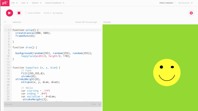
p5 .js is a JavaScript library that starts with the original goal of Processing—to make coding accessible for artists, designers, educators, and beginners—and reinterprets this for today's web. Using the original metaphor of a software sketchbook,  p5 .js has a full set of drawing functionality. Helpful links:  https://p5js.org/reference/#/p5/color Test circle animation:  Code in p5:  https://editor.p5js.org/heestar/sketches/bTSm0YbHg Final:  https://editor.p5js.org/heestar/full/bTSm0YbHg Code in p5:  https://editor.p5js.org/heestar/sketches/KR0IQi8_5 Final here is what I created winking smiley face: https://editor.p5js.org/heestar/full/KR0IQi8_5

On/Off & In-Between

Image
BLOG 1 To do:  Create circuit that makes use of Analog inputs and outputs where the interaction centers anywhere except the hands. If you choose to use hands then try getting your hands on an analog sensor that is NOT a potentiometer. I created a circuit using analog inputs and outputs. Most ticky part of this exercise was to had to write the correct coding.  const int ledPin = 9;       // pin that the LED is attached to int analogValue = 0;        // value read from the pot int brightness = 0;         // PWM pin that the LED is on. void setup () { // initialize serial communications at 9600 bps:      Serial.begin(9600);      // declare the led pin as an output:      pinMode (ledPin, OUTPUT ); } void loop () {     analogValue = analogRead (A0);    // read the pot value      brightness = analogValue /4;       //divide by 4 to fit in a byte      analogWrite (ledPin, brightness);   // PWM the LED with the brightness value

Input/Output

Image
TO DO:  Create another circuit or modify your existing circuit, this time using the Arduino to read your input and to affect your output. This assignment was a little confusing for me. When I attempt to do it the first time I failed. But once I  study the schematic and really understand the circuit flow I began to process it.   - wire everything correctly, follow the schematic - input/output is connected to button and the main power source - Write the correct program so it responds accordingly.  - Sync the arduino with the code - connect and test The code commands the microcontroller to controls the system. Learning:  Microcontrollers are optimized for control of general input and output.  Controller  or  microcontroller  is usually reserved for a simple processor that does only one task, like listening to sensors.

First Circuit

Image
TO DO    Create your own simple circuit that activates with a switch you build from a conductive material. You can use the power and ground pins on your Arduino to power your circuit. The task was simple I need to find a conductive material to link the two power ( - & +) sources together to make the costume switch.  Once I understood the flow of the electronic circuit I looked for a found object that has the conductive components. I came across a couple of options. ( Pater Crips, Nails, any unused old material  trinkets   that could be used as the connector). I decided to use a key-shaped medallion to give a more analog feeling. I build a keyhole that could be used as a base which could hold the (-) hookup wire and connected the (+) hookup wire to the key-shaped medallion.  Learnings:  Electrical conductivity in metals is a result of the movement of electrically charged particles. The atoms of metal elements are characterized by the presence of valence electrons, which are e